Wideband FFT
Purpose
This FFT was originally sourced from ASTRON via OpenCores. It performs an N-Point Wideband FFT on data that is partly applied in serial and partly applied in parallel. This FFT specifically suits applications where the sample clock is higher than the DSP processing clock. For each output stream a subband statistic unit is included which can be read via the memory mapped interface.
This unit connects an incoming array of streaming interfaces to the wideband fft. The output of the wideband fft is connected to a set of subband statistics units. The statistics can be read via the memory mapped interface (TODO). A control unit takes care of the correct composition of the output streams(sop,eop,sync,bsn,err). These signals are optional and can be removed to only use the sync signal.
This unit only handles one sync at a time. Therefore the sync interval should be larger than the total pipeline stages of the wideband FFT.
Module Overview
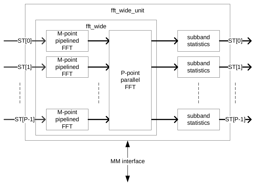
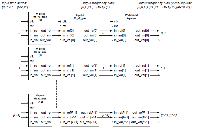
An overview of the fft_wide unit is shown in Figure 1. The fft_wide unit calculates a N-point FFT and has P number of input streams. Data of each input is offered to a M-point pipelined FFT, where M=N/P. The output of all pipelined FFTs is then connected to a P-point parallel FFT that performs the final stage of the wideband FFT. Each output of the parallel FFT is connected to a subband statistics unit that calculates the power in each subband. The MM interface is used to read out the subband statistics. The rTwoSDF pipelined FFT (see R2SDF FFT) design is used as building block for the development of the wideband extension.
Firmware Interface
Clock Domains
There are two clock domains used in the fft_wide unit: the mm_clk and the dp_clk domain. Figure 2 shows an overview of the clock domains in the fft_wide unit. The only unit that is connected to both clock domains is the memory of the subband statistics module. This memory is a dual ported ram that holds the results of the subband statistics. Table 1 lists both clocks and their characteristics.
Name |
Frequency (MHz) |
Description |
|---|---|---|
DP_CLK |
200 MHz |
Clock for datapath |
MM_CLK |
125 MHz |
Clock for mm interface |
Interface signals
Figure 2 shows the Simulink Wideband FFT block in its base configuration. In this form, it offers a minimal set of input/output ports that are comparable with what the CASPER FFT offers.
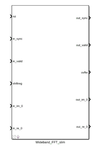
Figure 3 shows the Simulink Wideband FFT block in its expanded configuration which offers the bsn, sop, eop, error, empty and channel control signals. Their function is explained by the graph below.

The full set of signals available to the Simulink block are detailed in the table below.
Signal |
Type |
Size |
Description |
|---|---|---|---|
Reset |
std_logic |
1 |
Datapath reset. |
Clock enable |
std_logic |
1 |
Clock enable signal (used by Xilinx black box). |
Clock |
std_logic |
1 |
Datapath clock (used by Xilinx black box). |
Sync |
std_logic |
1 |
In/out sync pulse, preceeds data by 1 clock cycle. |
Valid |
std_logic |
1 |
In/out valid data signal. Goes high with first valid data sample. |
Shiftreg |
std_logic_vector |
\(\log2(nof\_points)\) |
Bit vector dictating at which stages to shift in an N-point FFT. A ‘1’ indicates a shift while a ‘0’ indicates no shift at that stage. |
Ovflw |
std_logic_vector |
\(\log2(nof\_points)\) |
Bit vector dictating at which stages overflow occured in an N-point FFT. A ‘1’ indicates an overflow while a ‘0’ indicates no overflow at that stage. |
bsn |
std_logic_vector |
64 |
A timestamp identification port for the data. |
sop |
std_logic |
1 |
A start-of-packet indicator (see figure 4 for detail). |
eop |
std_logic |
1 |
An end-of-packet indicator (see figure 4 for detail). |
Empty |
std_logic_vector |
16 |
Empty signal for the sosi data packet. |
Error |
std_logic_vector |
32 |
Error indicator giving 32 different one-hot encoded errors. |
Channels |
std_logic_vector |
32 |
An indicator for mapping of channels to streams. |
Im |
std_logic_vector |
in_dat_w or out_dat_w |
Data port for either one polarisation (when doing a dual pol FFT), or the imaginary part (when doing a complex FFT). |
Re |
std_logic_vector |
in_dat_w or out_dat_w |
Data port for either one polarisation (when doing a dual pol FFT), or the real part (when doing a complex FFT). |
Complex FFT
For complex input use_separate = false. When use_reorder=true then the output bins of the FFT are re-ordered to undo the bit-reversed (or bit-flipped) default radix 2 FFT output order. The fft_r2_wide then outputs first 0 Hz and the positive frequencies and then the negative frequencies. The use_reorder is performed at both the pipelined stage and the parallel stage.
When use_fft_shift=true then the fft_r2_wide then outputs the frequency bins in incrementing order, so first the negative frequencies, then 0 Hz and then the positive frequencies. When use_fft_shift = true then also use_reorder must be true.
Two Real FFT’s
When use_separate=true then the fft_r2_wide can be used to process two real streams. The first real stream (A) presented on the real input, the second real stream (B) presented on the imaginary input. The separation unit outputs the spectrum of A and B in an alternating way. When use_separate = true then also use_reorder must be true. When use_separate = true then the use_fft_shift must be false, because fft_shift() only applies to spectra for complex input.
Remarks
This FFT supports a wb_factor = 1 (= only a fft_r2_pipe instance) or wb_factor = g_fft.nof_points (= only a fft_r2_par instance). Care must be taken to properly account for guard_w and out_gain_w, therefore it is best to simply use a structural approach that generates seperate instances for each case:
wb_factor = 1 –> pipelined FFT
wb_factor > 1 AND wb_factor < g_fft.nof_points –> wideband FFT
wb_factor = g_fft.nof_points –> parallel FFT
This FFT uses the use_reorder in the pipeline FFT, in the parallel FFT and also has reorder memory in the fft_sepa_wide instance. The reorder memories in the FFTs can maybe be saved by using only the reorder memory in the fft_sepa_wide instance. This would require changing the indexing in fft_sepa_wide instance (TODO).
The reorder memory in the pipeline FFT, parallel FFT and in the fft_sepa_wide could make reuse of a reorder component from the reorder library instead of using a dedicated local solution (TODO).
Parameters
Both the wideband and pipelined FFT’s offer a set of parameters for control over the FFT’s characteristics, data handling and implementation on the FPGA. These are tabulated below.
FFT parameters
Generic |
Type |
Value |
Description |
|---|---|---|---|
Bit-reverse output |
Boolean |
true |
When set to ‘true’, the output bins of the FFT are reordered in such a way that the first bin represents the lowest frequency and the highest bin represents the highest frequency. |
Reorder frequencies |
Boolean |
false |
False for [0, pos, neg] bin frequencies order, true for [neg, 0, pos] bin frequencies order in case of complex input |
Separate complex in/out ports? |
Boolean |
true |
When set to ‘true’ a separate algorithm will be enabled in order to retrieve two separate spectra from the output of the complex FFT in case both the real and imaginary input of the complex FFT are fed with two independent real signals. |
Nof channels |
Natural |
0 |
Defines the number of channels (=time-multiplexed input signals). The number of channels is \(2^{nof\_channels}\). Multiple channels is only supported by the pipelined FFT. |
Wideband factor |
Natural |
4 |
The number that defines the wideband factor. It defines the number of parallel pipelined FFTs. |
Number of points |
Natural |
1024 |
The number of points of the FFT. The number of points is \(2^{nof\_points}\). |
Extra control signals |
Boolean |
false |
Checking this box enables the usage of addition signals. See WB Arch for detail on these ports. |
Data parameters
Generic |
Type |
Value |
Description |
|---|---|---|---|
Input data width |
Natural |
8 |
Width in bits of the input data. This value specifies the width of both the real and the imaginary part. |
out_dat_w |
Natural |
14 |
The bitwidth of the real and imaginary part of the output of the FFT. The relation with the in_dat_w is as follows: \(out\_dat\_w=in\_dat\_w+(\log2(nof\_N))/{2+1}\). |
stage_dat_w |
Natural |
18 |
The bitwidth of the data that is used between the stages (=DSP multiplier-width). |
guard_w |
Natural |
2 |
Number of bits that function as guard bits. The guard bits are required to avoid overflow in the first two stages of the FFT. |
guard_enable |
Boolean |
true |
When set to ‘true’ the input is guarded during the input resize function, when set to ‘false’ the input is not guarded, but the scaling is not skipped on the last stages of the FFT (based on the value of guard_w). |
Rounding behaviour |
String |
“ROUND” |
Gives control over the removal of the least significant bits when requantising. See WB Quant for further detail. Options are “ROUND” or “TRUNCATE”. |
Overflow behaviour |
String |
“WRAP” |
Gives control over the removal of the most significant bits when requantising. See WB Quant for further detail. Options are “WRAP” and “SATURATE”. |
Synth/Imp Parameters
Generic |
Type |
Value |
Description |
|---|---|---|---|
Use DSP for Cmults |
String |
“YES” |
Sets the Xilinx use_dsp directive to force usage or non-usage of DSP48 elements when synthesizing/implementing the complex multipliers. |
Cmult options |
String |
“4DSP” |
Sets which complex multipliers are used in the FFT. Options are “3DSP” for a Gaussian complex multiplication instantiation that uses 3 DSP48 elements or “4DSP” for a classic complex multiplication that uses 4 DSP48 elements. |
Vendor |
Natural |
0 |
0 for Xilinx FPGA’s, 1 for Intel FPGA’s. |
RAM primitive |
STRING |
“auto” |
Parameter for the xpm BRAM module which will dictate how BRAM’s are implemented on the FPGA. Options are “auto”, “distributed”, “ultra” and “block”. |
FIFO primitive |
STRING |
“auto” |
Parameter for the xpm FIFO module which will dictate how FIFO’s are implemented on the FPGA. Options are “auto”, “distributed”, “ultra” and “block”. |
Module Architecture
Several subdesigns were defined in order to create the eventual wideband decimation in frequency (DIF) FFT. These sub-designs are:
Complex Pipelined FFT for two real inputs (fft_r2_pipe).
Complex Parallel FFT for two real inputs (fft_r2_par).
Complex Wideband FFT for two real inputs (fft_r2_wide).
fft_r2_pipe
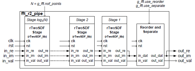
The architecture for a pipelined FFT is based on design units from the rTwoSDF_lib and is basically the same as the rTwoSDF unit. The difference with respect to the rTwoSDF unit is that the fft_r2_pipe unit must be capable of processing two real inputs as well. Therefore the archtectural block diagram is extended with an optional separate function. Figure 4 gives an archtectural overview of the design.
fft_r2_par
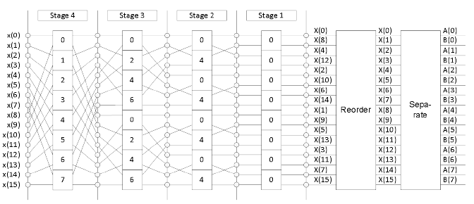
In the case of a parallel FFT, all time domain samples for a slice come in parallel and therefore all multiplications and additions have to be performed in parallel as well. The architecture for a parallel for a parallel FFT is shown in Figure 5. In Figure 5, the number of points is set to 16. Each square represents an optimised complex butterfly. The numbers in the butterfly refer to the exponent k in \(W_N^k\) (the twiddle factors). The parallel FFT is also capable of reordering the output data and processing two real inputs. Therefore a parallel reorder and parallel separate function are defined as well.
fft_r2_wide
The wideband variant of the FFT is partly pipelined and partly composed in parallel. The amount of parallelization is specified by P (wideband factor). The architecture is shown in Figure 6. The reorder functionality is inherited from both the fft_r2_par and fft_r2_pipe units, but for the separation functionality a dedicated wideband variant must be designed.
Quantisation
Requantisation is required for every butterfly in the FFT. With the FFT being a DIF FFT, the butterfly operation is shown in Figure 7 and it’s algorithmic operation is detailed below:
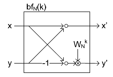
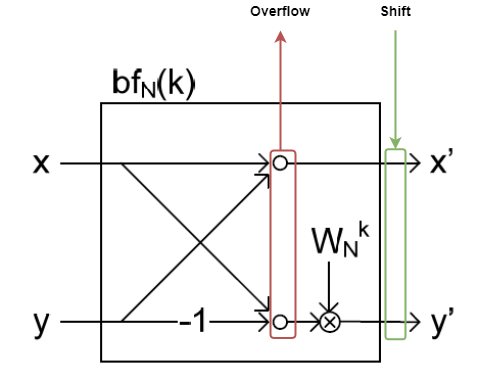
Each butterfly performs an addition and multiplication. For fixed point number systems of values in the range \((0.5, -0.5]\) we get MSB growth from additions and LSB growth from multiplications. The LSB growth from multiplication may be sliced away (which introduces minor effects due to the rounding scheme). This wideband FFT offers the option to truncate or round away from zero (TODO: introduce even rounding). MSB growth from addition will cause overflow that may be handled in two ways: SATURATE the value or WRAP it. Wrapping will use no logic while saturation will require logic to prevent natural wrapping. Ideally however, the effect of overflow in the FFT is irreversible and as such should be prevented. This is done by scaling the data by 2 before entry into each stage, and by extension each butterfly operating in parallel for that stage. Fine-control over which stages the FFT should apply a shift for is possible by populating the shiftregister port. Should overflow occur in any of the butterflies in the FFT, the overflow register will populate that bit-index with a ‘1’. Figure 8 shows the location of the overflow reporting and shift within the butterfly.
The shift operation acts on value \(A\) as:
where \(round()\) is a function that rounds the value \(A\) according to the “Rounding behaviour” specified see WB FFT Params.
Overflow is detected in a stage by inspecting the sign of the input to the adder and sign of the output. This check differs depending on whether a subtraction or addition is being performed. The following VHDL snippets make this check (TODO):