Wideband PFB
Purpose
The wpfb unit is a Wideband Poly Phase FilterBank which can process a datastream that is partly applied in serial and partly applied in parallel. It consists of a Poly Phase Filter (PPF) and a Fast Fourier Transform (FFT). The wpfb distinguishes from a single FFT by the PPF that functions as a window function in order to produce a flat response across the channel, but also provides excellent suppression of out-of-band signals.
Module Overview
An overview of the wpfb unit is shown in Figure 1. The wpfb is build out of two N-point wideband PPFs (one for the real input and one for the imaginary input) and a single N-point wideband FFT. All P outputs are connected to a subband statistic unit that calculates the power in each subband. The MM interface is used to read and write the filter coefficients and to read out the subband statistics (still to be done).
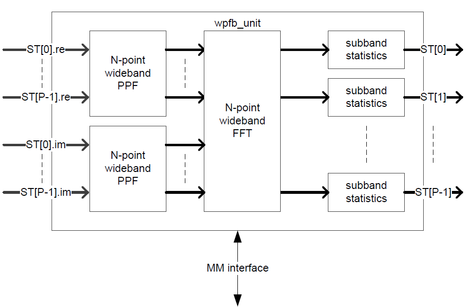
A control unit takes care of the correct composition of the control of the output streams regarding sop, eop, sync, bsn, err. The wpfb unit can handle a wideband factor \(>= 1\) or a narrowband factor \(>= 1\) (\(2^{nof\_chan}\)).
For wideband factor = 1 the WPFB uses a pipelined FFT.
For wideband factor > 1 the WPFB uses a wideband FFT.
For wideband factor >= 1 the WPFB supports setting the number of channels >= 0, even though the concept of channels is typically not useful when wideband factor > 1.
The WPFB does support the binary reordering of data after the FFT.
The WPFB can perform a complex FFT or 2 Real to 2 Complex FFT.
The WPFB does support input flow control using the extra control signals, with support for gaps in the time input.
Firmware Interface
Clock Domains
As with the wideband_fft, the WPFB has a mm_clk and a dp_clk though as with the wideband_fft, since no memory-mapping is supported as yet, the PFB only makes use of the dp_clk (200MHz).
Interface signals
Figure 2 shows the Simulink Wideband FFT block in its base configuration. In this form, it offers a minimal set of input/output ports that are comparable with what the CASPER FFT offers.
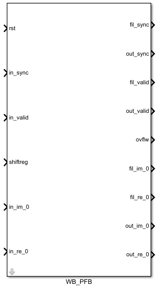
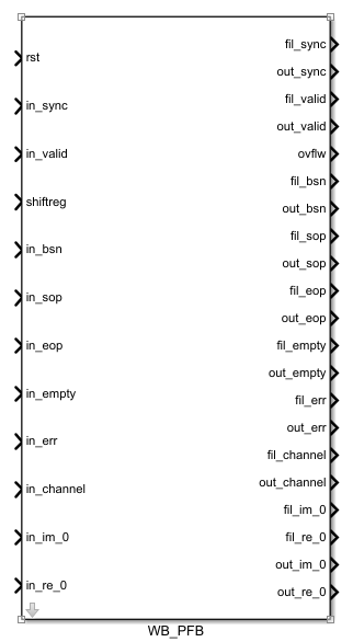
Figure 3 shows the Simulink Wideband FFT block in its expanded configuration which offers the bsn, sop, eop, error, empty and channel control signals. Their function is explained by the graph below.
The full set of signals available to the Simulink block are detailed in the table below.
Signal |
Type |
Size |
Description |
|---|---|---|---|
Reset |
std_logic |
1 |
Datapath reset. |
Clock enable |
std_logic |
1 |
Clock enable signal (used by Xilinx black box). |
Clock |
std_logic |
1 |
Datapath clock (used by Xilinx black box). |
Sync |
std_logic |
1 |
In/out sync pulse, preceeds data by 1 clock cycle. |
Valid |
std_logic |
1 |
In/out valid data signal. Goes high with first valid data sample. |
Shiftreg |
std_logic_vector |
\(\log2(nof\_points)\) |
Bit vector dictating at which stages to shift in an N-point FFT. A ‘1’ indicates a shift while a ‘0’ indicates no shift at that stage. |
Ovflw |
std_logic_vector |
\(\log2(nof\_points)\) |
Bit vector dictating at which stages overflow occured in an N-point FFT. A ‘1’ indicates an overflow while a ‘0’ indicates no overflow at that stage. |
bsn |
std_logic_vector |
64 |
A timestamp identification port for the data. |
sop |
std_logic |
1 |
A start-of-packet indicator (see figure 4 for detail). |
eop |
std_logic |
1 |
An end-of-packet indicator (see figure 4 for detail). |
Empty |
std_logic_vector |
16 |
Empty signal for the sosi data packet. |
Error |
std_logic_vector |
32 |
Error indicator giving 32 different one-hot encoded errors. |
Channels |
std_logic_vector |
32 |
An indicator for mapping of channels to streams. |
Im |
std_logic_vector |
in_dat_w or out_dat_w |
Data port for either one polarisation (when doing a dual pol FFT), or the imaginary part (when doing a complex FFT). |
Re |
std_logic_vector |
in_dat_w or out_dat_w |
Data port for either one polarisation (when doing a dual pol FFT), or the real part (when doing a complex FFT). |
The wideband PFB extends the _WB FFT functionality to perform a complex or two real FFT. It further follows the same protocol for wb_factor control.
Parameters
Control over the PFB’s characteristics, data handling and implementation on the FPGA are tabulated below: